|
|
||
|---|---|---|
| kicad | ||
| library@00e9790a22 | ||
| picture | ||
| .gitignore | ||
| .gitmodules | ||
| .qeda.yaml | ||
| CHANGELOG.md | ||
| DEVELOPMENT.md | ||
| JLCPCB_CORRECTION.csv | ||
| LICENSE.txt | ||
| Makefile | ||
| README.md | ||
| bom.ini | ||
| fp-lib-table | ||
| pd_blocker.kicad_pcb | ||
| pd_blocker.kicad_pro | ||
| pd_blocker.kicad_sch | ||
| refdes2fab.py | ||
| sym-lib-table | ||
| version | ||
README.md
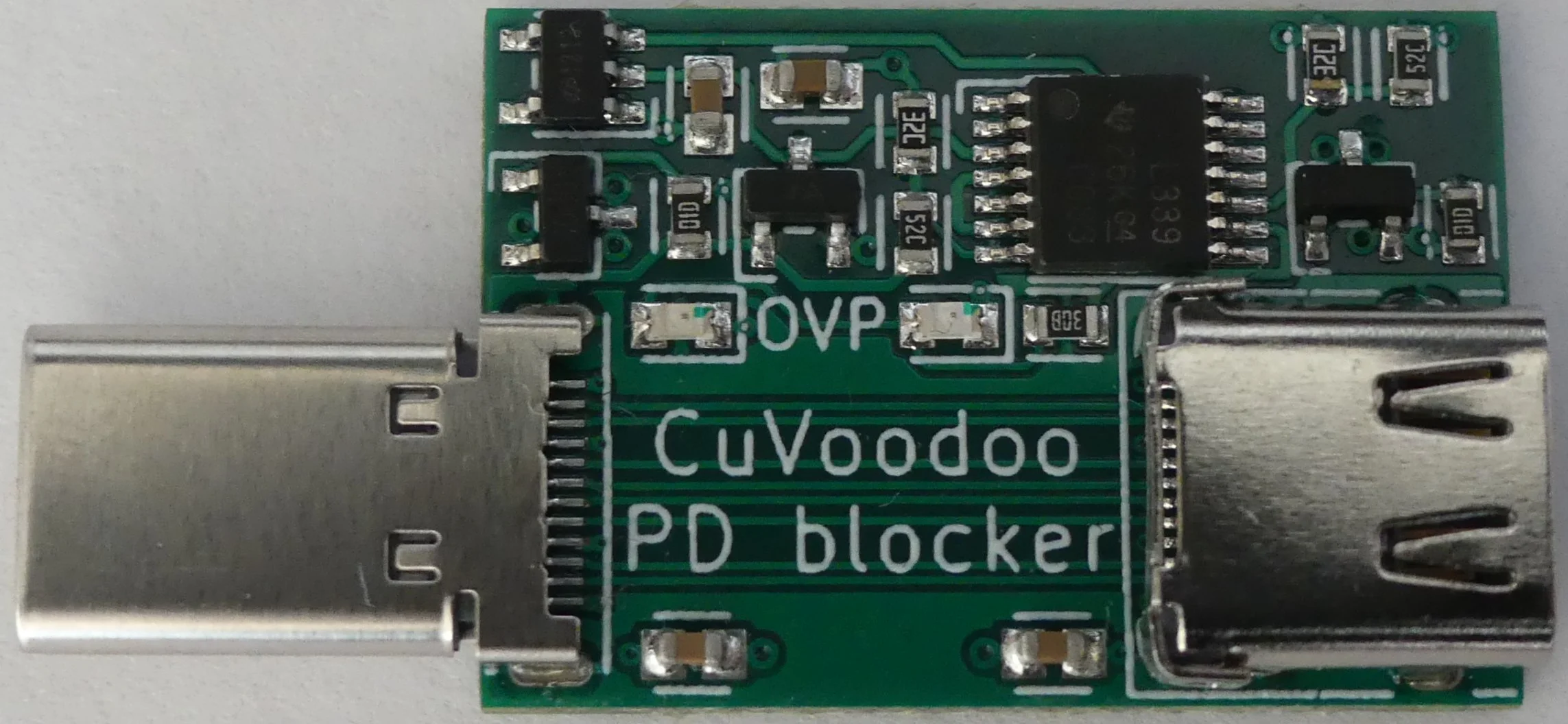
The PD blocker removes Power Delivery (PD) capabilities from USB-C connections and provides over-voltage protection.


purpose
Some USB-C devices do not require the Power Delivery features available on USB-C, mainly higher voltage and current. The device could not even be rated for higher voltages. But chargers might be stuck at higher voltage, or mischievous eMarked cables (with PD-capable chips built in) could raise the voltage, permanently damaging it.
The PD blocker protects your [expensive] USB-C device from such damages.
usage
Insert the PD blocker in line, between the power source (e.g. charger or host computer), cable, and your device. It can be inserted between any two of these components, and will work the same. Plug and receptacle can be either side, and it is reversible along the axis of the connectors (like normal USB-C connectors).
The PD blocker will prevent any Power Delivery communication, such as raising the voltage. And when over-voltage is detected (Vbus > 5.5V), power is cut and an OVP LED indicating the culprit side lights up. Connect the PD blocker before the target device for the protection to take effect before it can reach it.
All other features of USB-C are preserved (e.g. USB2, USB3, USB4, SBU, orientation detection) Some alternate modes requiring PD communication will not work anymore though.
mode of operation
To prevent PD communication, capacitors are placed on the CC lines. They smooth out the 300 Kbps BMC signal used for PD communication. It still allows the identification of Rp, Rd, and Ra used for orientation and role detection.
Additionally there is an over-voltage protection circuit. VBUS (on either side) is compared to a reference voltage. When VBUS is below 5.5V, p-channel MOSFETs are switched on, and allow VBUS going from one side to the other. When VBUS is above 5.5V, the p-channel MOSFETs are switched off, and prevent VBUS interconnection, cutting the power.
warning
The PD blocker can block up to 36V. PD rev 2.0 specifies voltages up to 20V. PD rev 3.0 specifies voltages up to 48V, but I haven't seen any power source using this new capability yet.
The PD blocker can take a seconds (at 5.6V) until the over-voltage protection take effect. Connect the PD blocker before the target device for the protection to take effect before it can reach it.