6.2 KiB
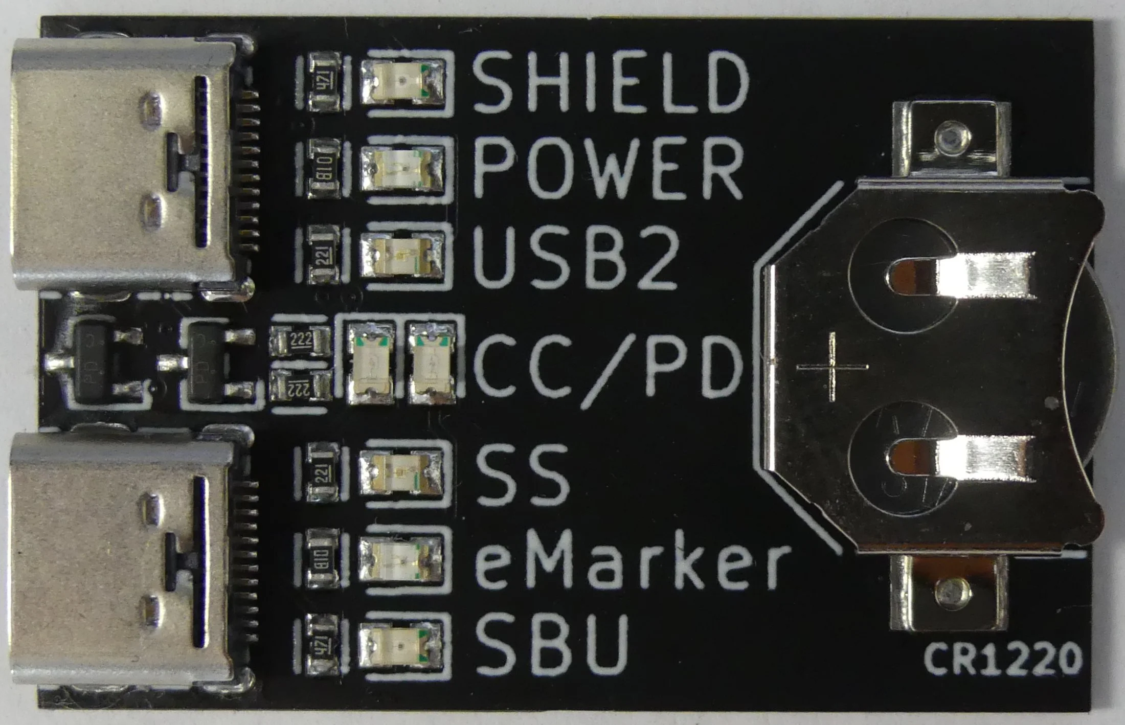
The USB-C cable tester shows which features a USB-C to USB-C cable supports.


purpose
USB-C cables come in a several flavours. The USB Type-C Cable and Connector Specification lists two types of cables:
- Standard: this supports USB 2.0 data transfer, as well as Power Delivery (PD)
- Full-Featured: this adds differential pairs used for SuperSpeed (SS) data transfer (for USB3, USB4, ...), and sideband use (SBU) for alternate modes or USB4 data transfer
On top of that, cables can be electronically marked (eMarked). Full-Featured cables should be electronically marked, while this in optional for standard cables. eMarked cables include chips that communicate on the CC wire using the PD protocol. They provide information about the cable, and are mandatory (but not sufficient) for 5A current transfer (e.g. for 100W charging) instead of the standard 3A (e.g. 60W). Then there are not specification compliant cables, that only support charging, or no PD communication.
Because what is inside of the cable is not indicated on the outside, the cable tester checks for the individual capabilities. I suspect some full-featured cables are not electronically marked, and non-5A marked cables are sparse. And most magnetic cables are not shielded, at least not from plug to plug.
usage
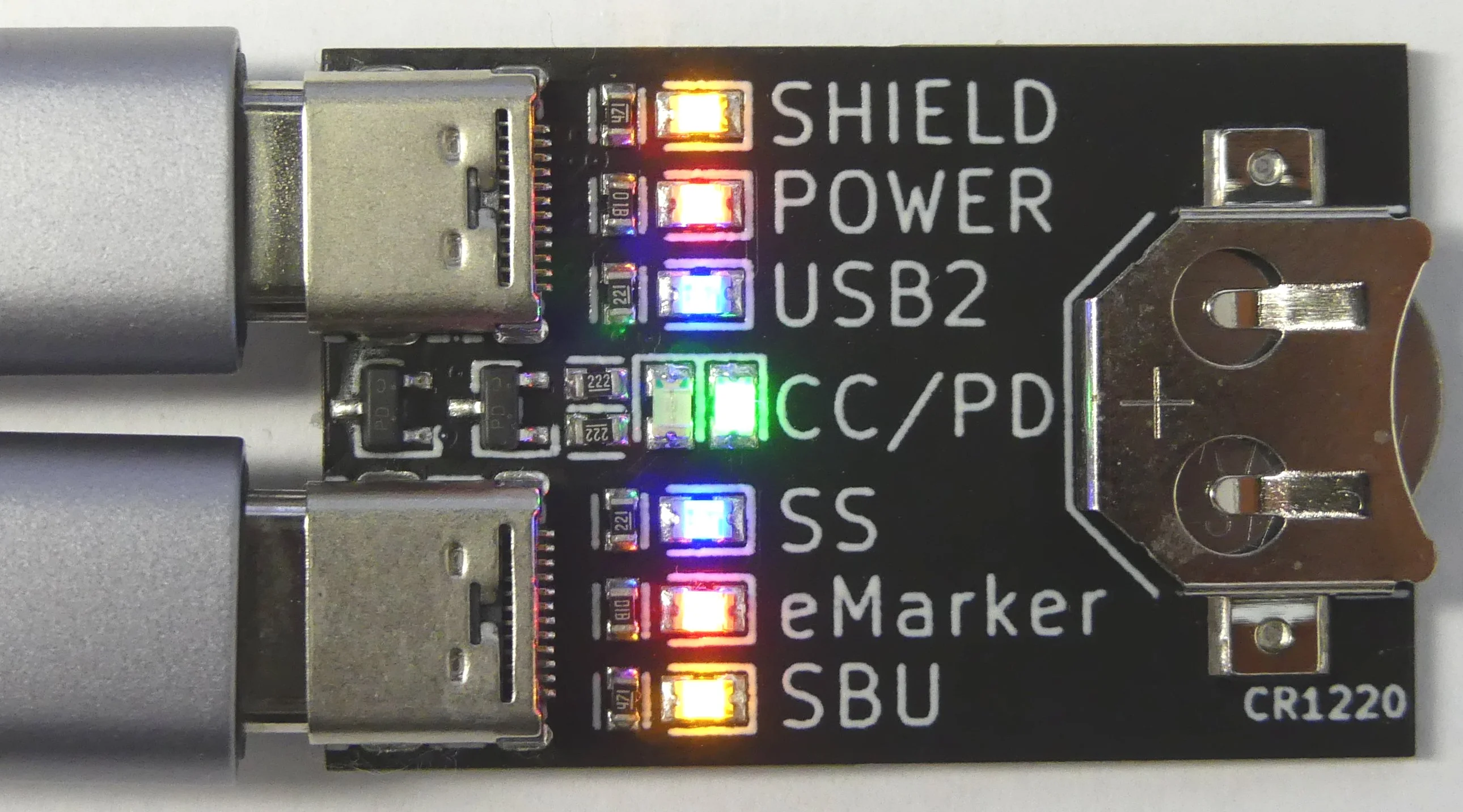
Plug both ends of the USB-C cable in the tester and read the lights:

- SHIELD: ensures the cable is shielded, important for super speed data transfer.
- POWER: ensures the VBUS and GND wires are present, required to power a device.
- USB2: ensures the D+ and D- wires are present, required for USB data transfer (up to at least 2.0).
- CC/PD: ensures the Configuration Channel (CC) wire is present, required to determine the plug orientation and for Power Delivery (PD) communication (used for fast charging)
- SS: ensure the 4 differential pairs are present, required for Super Speed (SS) data transfer (USB3, USB4, ...)
- SBU: ensures the Side Band Use (SBU) wires are present, used for alternate modes.
- eMarker: indicates if the cable is electronically marked, required to support 5A/100W power transfer.
Note: the eMarker indication does not mean the cable does support 5A/100W power transfer. Most of the time, an electronically marked cable does support 5A, since the chip costs more than the wire. This information needs to be read out from the chip inside the cable using the PD protocol. The cable tester does not support this functionality. Some USB Power Monitor (UPM) provide this functionality.
mode of operation
Here the methods used to test the different capabilities of the cable:
-
POWER: ensures the VBUS and GND wires are present in the cable, required to power a device. Although there 4 ground and 4 power pins, there are only 1 ground and 1 power wires. The pins are inter-connected in the plugs on each side of the cable.
-
SHIELD: ensures the shell of the plugs are connected on both sides of the cable. This does not ensure if there is really a shield in the cable, or just a wire. It also can't ensure the shell is simply shorted to GND. These limitations are outside of the scope of this tester since I haven't seen any cable cheating this way. Also, If the cable has a shield, but only connected one plug, this will not be detected.
-
USB2: ensures the UTP wire are present, used for USB 2.0 data transfer. There is only one pair of UTP wire for the Dp and Dn signals using for USB 2.0 communication, connected to A6 and A7 on both sides. Since the plug is reversible on both sides, we short the pins to be sure we can test the cable.
-
SS: ensures the SuperSpeed (SS) wires are present, for USB3 (and USB4) data transfer. There are 4 pairs of wires (SDPxx) used for differentials signals. The tester checks if all are present.
-
SBU: ensures the sideband use (SBU) are present, used for Alternate Modes. There are 2 single SBU wires. The tester checks if all are present.
-
CC: ensures the Configuration Channel is present, used for Power Delivery (PD) communication. There is one wire going from CC1 on one side of the connector, to CC1 on the other side of the connector. Since the plug on both sides is reversible, there are 4 possible permutations. This pin is actually used to determine the orientation of the plug, and do the date signal switching on the right pins.
-
eMarker: indicates if the cable is electronically marked. The detection is the complicated part of this design. A5 on both sides are interconnected through the CC wire. B5 on both sides are connected to Vconn. Vconn only allows to power the embedded chip, but does not provide B5 interconnection. The connected device can detect the presence of the chip, by checking if B5 (on each side) is pulled down using Ra (~ 1kOhm). It can then provide power on Vconn. The cable tester detects electronically marked cables the following way. If Ra is present, the gate voltage of a p-channel MOSFET on the tester is pulled low, powering the corresponding LED. By default the gate is pulled up by the resistor used for the CC LED. When Ra is present, it is on both plugs of the cable. Thus it is enough to detect is on one plug. Because it can be on A5 or B5 pins, the detection circuit needs to be on both pins. On the other plug, the CC pins can't be interconnected, else the voltages is pulled to low for the CC LED to work. Thus, two separate LEDs are used to detect CC. The pull-up resistor needs to be as high as possible to, for the Ra pull-down resistor (800-1200 Ohm) to work properly, activating the gate. The BSS84 pMOS has a Vgs of ~1.7V. A pull-up resistor of 2.2 kOhm is sufficient (with a 3V battery). Green LEDs are used for CC. Although they have a higher voltage drop, they seems to be more efficient. With a 2.2 kOhm, it produces a bright enough light. Warning: because green LED has a forward voltage drop of ~2V to ground, the battery voltage can't be higher than 3.3V, else the gate voltage will exceed the threshold and the eMarker LED will be on, which is a false positive.