|
|
||
|---|---|---|
| coraleda/subc | ||
| geda/symbols | ||
| library@50a1bf7ccf | ||
| picture | ||
| .gitignore | ||
| .gitmodules | ||
| .qeda.yaml | ||
| CHANGELOG.md | ||
| DEVELOPMENT.md | ||
| LICENSE.txt | ||
| README.md | ||
| Rakefile | ||
| gafrc | ||
| mass_prop.sh | ||
| micro-usb_cable_tester.lht | ||
| micro-usb_cable_tester.sch | ||
| pnp_fab.tab | ||
| version | ||
README.md
The micro-USB cable tester verifies if a USB 2.0 cable with micro-B plug can be used to transfer data, or just for charging.


purpose
Have you ever plugged in a device using a micro-USB cable and wondered why you can't see it on your computer? Especially when you are developing the USB stack of a micro-controller. This tiny gadget will test the cable and confirm if it can be used to transfer data. Now you can be sure your USB implementation needs some tweaking, and not waste time because this cable was only for charging.
usage
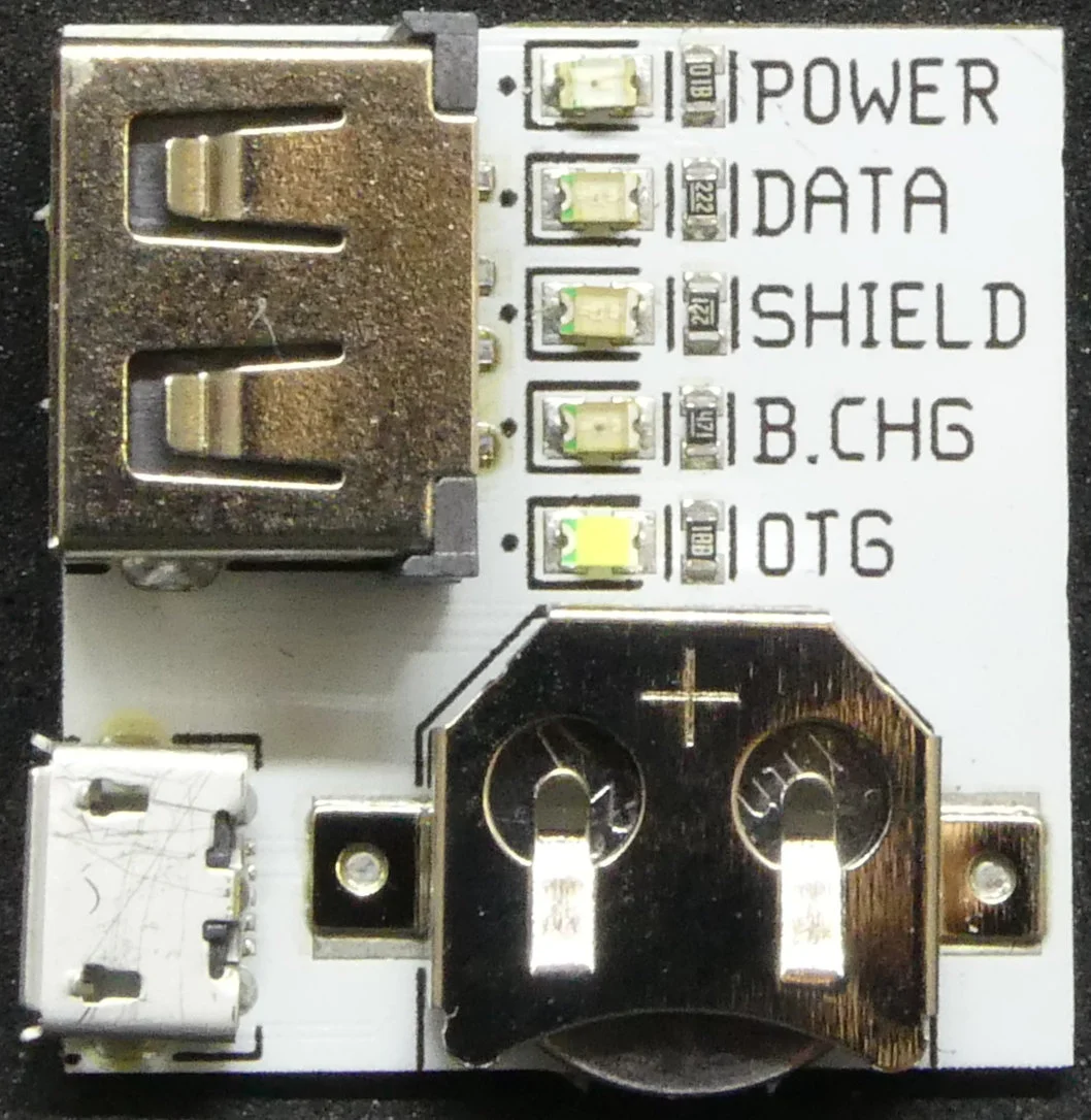
Pictures of the device are available on the wiki.
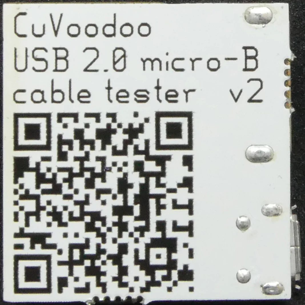
Ensure a CR1220 coin cell is present in the holder on the back of the board. A CR1220 coin cell is provided with the tester.
Plug in the USB type A of the cable at the top, and the USB type micro-B at the bottom:
- when the red POWER LED lights up, the cable can be used to power a device (with up to 500 mA, according to USB 2.0 specification)
- when the green DATA LED lights up, the cable can be used to transfer data
- when the blue SHIELD LED lights up, the cable can be used for data transfer with High Speed devices (480 Mbit/s), else this cable should only be used for Full Speed devices (12 Mbit/s). If the DATA LED is not on at the same time, the cable is defective
- when the orange B.CHG (battery charging) LED lights up, the cable can be used to charge a device (with up to 1.5 A, according to USB Battery Charging 1.2 specification). This cable can not be used to transfer data. If the POWER LED is not on at the same time, the cable is defective
- when the white OTG LED lights up, this is a On-The-Go cable meant to connect a device (i.e. a memory stick) to a host with micro-B port (e.g. a phone). Such adapters can be tested without plugging in the type-A side
battery charging
Normally USB cables capable of data transfer should always be used (USB specification compliant cables), and the charger port the cable is plugged into indicates the device can draw up to 1.5 A by shorting the data lines (D+ and D-). This is known as a Dedicated Charging Port (DCP). Because most USB ports capable of providing more than 500 mA are common practice now, some penny pincher though it was a good idea to short the data lines directly in the micro-B plug, and save the cost of the two additional wires for data transfer (along with shielding and controlled impedance). Such cables are often provided to charge battery operated devices. As described in purpose, I built the tester mainly to identify such cables and avoid using them for data transfer.
tip
After identifying the cable with this tester, I write the result using a marker on the cable with a letter: P for power only, C for battery charging, D for data without shield, S for shields cables, and O oft OTG adapter. This allows me to immediately know what the cable is capable of next time I use it.
mode of operation
Here the methods used to test the different capabilities of the cable:
- POWER: ensures the VBUS and GND wires are present in the cable, required to power a device. Signal path: VCC -> micro-B_VBUS -> A_VBUS -> LED -> A_GND -> micro-B_GND -> GND.
- DATA: ensures the D- wire is present in the cable, required to transfer data. The D+ is also required, but when D- is present, I expect D+ to also be. This is not the case if the cable is broken though, but this is not in the scope of this tester. Signal path: VCC -> micro-B_D- -> A_D- -> LED -> A_GND -> micro-B_GND -> GND.
- B.CHG: checks if D+ and D- are shorted in the micro-B plug. Signal path: VCC -> micro-B_D- -> micro-B_D+ -> LED -> GND.
- SHIELD: ensures the shell of the plugs are connected on both sides of the cable. This does not ensure if there is really a shield in the cable, or just a wire. It also can't ensure the shell is simply shorted to GND. These limitations are outside of the scope of this tester since I haven't seen any cable cheating this way. Signal path: VCC -> micro-B_VBUS -> A_VBUS -> LED -> A_GND -> micro-B_GND -> GND.
- OTG: checks if the ID pin is connected to ground, indicating the "device" that it should act as host. Signal path: VCC -> LED -> micro-B_ID -> micro-B_GND -> GND.
All details are in the schematic.
releases
Release archives with production output files are available on the wiki.