|
|
||
|---|---|---|
| kicad | ||
| library@14de4004fd | ||
| pictures | ||
| .gitignore | ||
| .gitmodules | ||
| .qeda.yaml | ||
| CHANGELOG.md | ||
| DEVELOPMENT.md | ||
| FLASHING.md | ||
| INSTALLATION.md | ||
| KiBOM_CLI.py | ||
| LICENSE.txt | ||
| Makefile | ||
| ORIGIN.md | ||
| README.md | ||
| TESTING.md | ||
| bom.ini | ||
| fp-lib-table | ||
| sym-lib-table | ||
| version | ||
| wled_chain.kicad_pcb | ||
| wled_chain.kicad_pro | ||
| wled_chain.kicad_sch | ||
README.md
WLED chain is a board for the WLED firmware, allowing to power, control, and chain them over Ethernet cables.
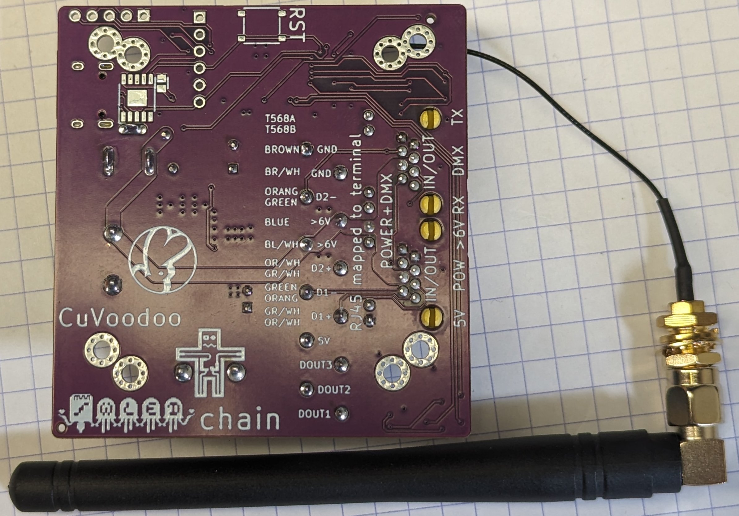
The boards can has a built-in antenna:\

Or have a connector for external antenna, for better reception or to be installed in metal enclosures:\

purpose
The WLED firmware is ideal to control addressable LEDs strip. WLED chain is a hardware board for it, matching my usage: robust remotely controlled LED strip based light installations for festivals. It allows to:
- use of the shelf 6-60V power supplies to power 5V LED strips
- inter-connect the boards to form long chains (only connecting the first to externally provided power and data)
- use cheap Ethernet CAT5E cables to inter-connect them (also over long distances)
- provide power and data (DMX512) over the Ethernet cables
- proper 5V LED data signal output (up to three of them)
- embed microphone for sound reactive effects
- put board in waterproof enclosure (for sonoff or generic 100x68x50 mm).
usage
status
On the RJ45 ports there are 4 LEDs. These indicate the status:
- on the right RJ45 port, indicating the status of power:
- the left LED indicates the >6V status: it is on when 6-60V power is provided to the board
- the right LED indicates the 5V status: it is on when the on-board DC-DC voltage regulator converts the 6-60V to 5V right after 6-60V is plugged in, or when 5V power is provided externally
- on the left RJ45 port, indicating the status of DMX traffic:
- the right LED indicates the DMX RX traffic: it is on (e.g. blinks rapidly) on DMX input traffic (when the board is configure as slave)
- the left LED indicates the DMX TX traffic: it is on(e.g. blinks rapidly) on DMX output traffic (when the board is configure as master)
There is an LED marked WLED on the top left of the board. It indicated the status of WLED:
- it switches every second when the access point is open (or could not connect to WiFi)
- it blinks at 1 Hz when connected to WiFi
- it blinks at 2 Hz when connected to MQTT (if the firmware supports MQTT)
On the top left corner of the board, there is a button labeled DL. This is configured as button 0 in WLED. It can be used to reset the configuration:
- hold it down for at least 6 seconds and the Wi-Fi settings will be reset to default
- hold it down for at least 12 seconds and the configuration memory is erased
installation
The board can be used in various configurations:
- LED strip (for small, medium, or large LED installations): using 5V, 12V, or 24V
- power supply: 5V or 6-60V
- enclosure: with or without a waterproof enclosure
- chain: a single standalone device, or with additional WLED chain devices
- DMX: controlled using WiFi, or DMX
The combination can be used for various installations.
power
The built-in 5V DC-DC converter is only rated up to 3A, limiting the total maximum output to 15W. This means you can power up to 3 meters of WS2812b 30 LEDs/m strip at full brightness. For more LEDs, limit the brightness in WLED, or use multiple boards and chain them. Voltage regulators capable of more current are rare and expensive. They are also less compact, would exceed the space available in the enclosure.
The initial design used a 5A capable voltage converter, but this current could not be sustained. Even with 90% high efficiency, the board could not handle passive dissipation of the generated heat. You could add a heat sink and fan when used outside the enclosure, but this is not the intended use.
If you need more than 3A continuously, you are exceeding the use case of this board. You can use multiple boards if you have separate LED strips, sharing the same 6-60V power supply. Else switch back to using an external 5V or 12V power supply and connect the LED strips directly to it. You can even power the board with the same 5V or 12V power supply using the DC jack (for 6-60V) or screw terminals (for 5V and 6-60V).
The 6-60V power input allows using any kind of power supply, like common 12V, 24V, or 48V. It also allows using 48V LiPo batteries (going up to 55V), to operate the devices without grid power.
There is an over current input protection of 1.8A using a PPTC. This is to protect the board from very bad accidents (e.g. shorted 5V output), and because Ethernet cables are no meant to carry power (PoE limit is 960 mA per pair, we are using two). To be able to power multiple WLED chain boards, each drawing up to 15W, use higher voltages (48V up to 60V).
The 6-60V input is also reverse polarity protected using an inline Schottky diode after the fuse. The 5V rail input/outputs is not reverse polarity protected. The onboard voltage regulator has an 3A over-current protection.
wiring
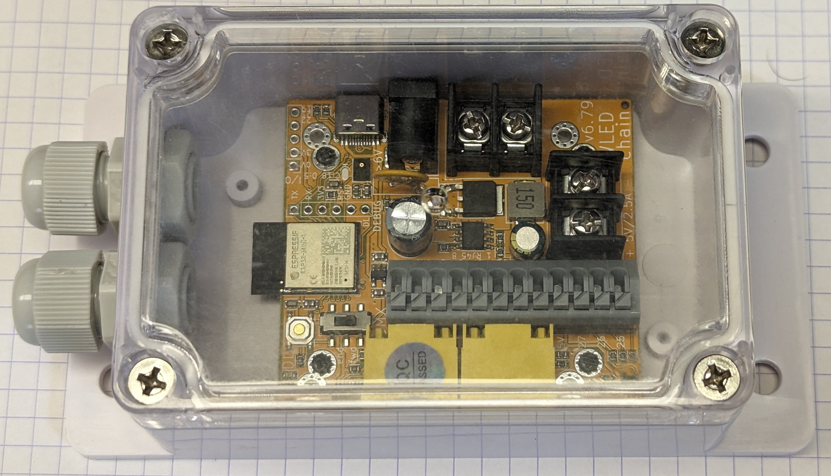
The board are primarily meant to be used with common sonoff enclosure. This provides protection against dust, metal induced shorts, and water. The board can be mounted using M2.5 self tapping screws to the enclosure. All cables inserted in the enclosure can be connected to the board while mounted in the enclosure using the terminals.
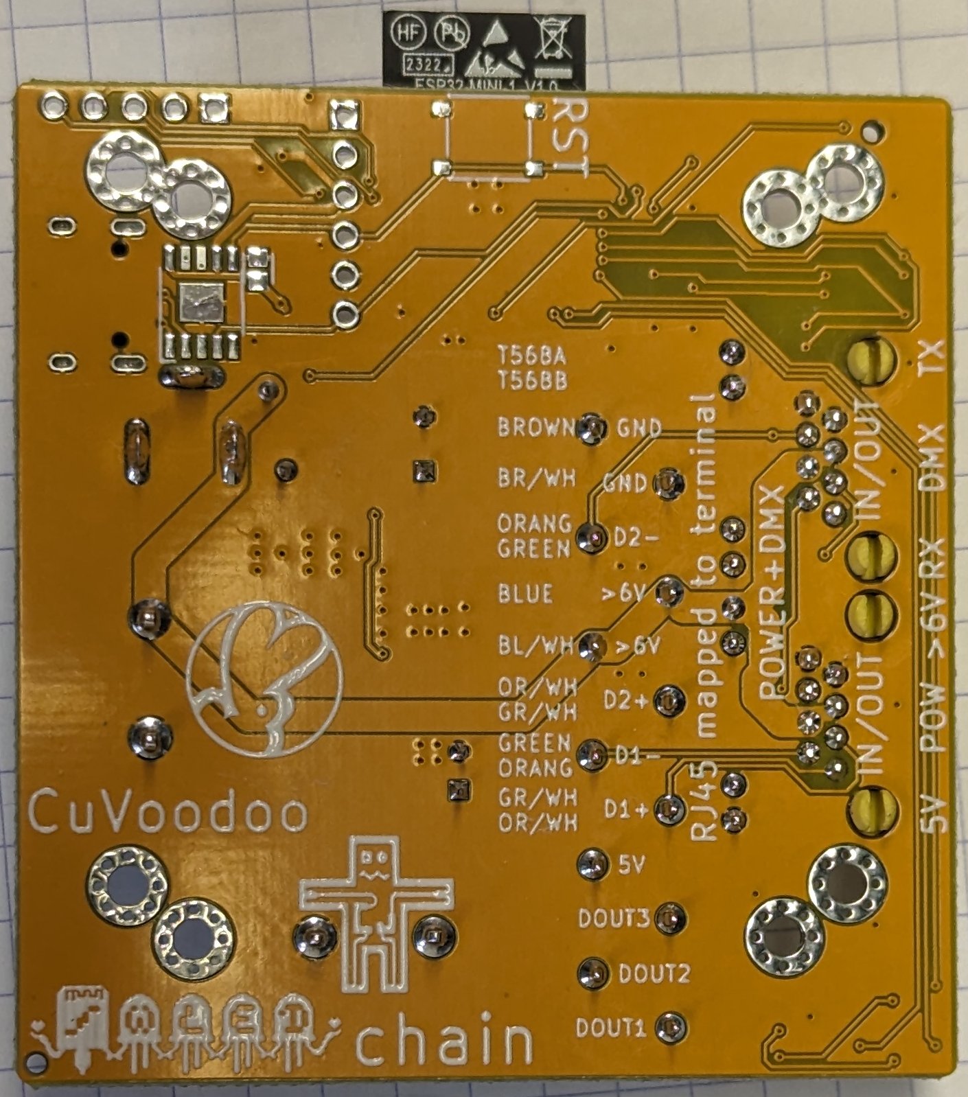
Since RJ45 8P8C connectors does not fit the PG7 glands, they need to be cut. The resulting wires can be inserted in the spring loaded terminal marked RJ45, following the pin numbering. The wire colors are also listed on the back of the board, in case it is already not mounted. In case boards need to be chained, two Ethernet cable can be inserted using the two glands, and the same number wires should be inserted together in the terminal.
6-60V power supply can be inserted using additional glands on the opposite side of the Ethernet cables. The wires should be connected using the screw terminal marked 6-60V. Follow the +/- indications on the board.
The LEDs strips cables can be inserted using additional glands on the opposite side of the Ethernet cables. The 5V and ground wire should be grouped together and connected using the screw terminal marked 5V. Follow the +/- indications on the board.
The data wire should be inserted in the spring loaded terminal marked LED DATA. The corresponding I/O configured in WLED is indicated on the side.
In case the board is not mounted in the enclosure, other ports can be used. 5V power can be provided through the USB port. 6-60V power input can be connected using the 2.1/5.5 mm ID/OD DC barrel jack. The Ethernet cables can be directly connected using the two RJ45 ports (either is fine as they are interconnected).
The USB, DC barrel, and RJ45 ports are not accessible when the board is in the enclosure simply because there isn't enough space. But feel free to add hole to the enclosure to access them. This would also remove the waterproof advantage though.
features
Features already implemented:
- daisy chain capability (providing data and power)
- built-in power 5V DC-DC converter (input up to 60V, output up to 3A)
- RS-485/DMX512 interface (not galvanicailly isolated)
- RJ45 port, providing power (PoE, passive, alternative B) and data (as used in DMX512), 2x for chaining capability
- RJ45 individual wires connector, using easy to insert spring loaded terminal, for allowing using Ethernet cable in waterproof enclosure, where the 8P8C connector does not fit through the PG7 cable gland
- DC barrel jack power input for 6-60V, for convenient use with off-the-shelves power bricks, allowing injecting power
- screw terminals for thicker wires, for larger power supplies and usage in waterproof enclosure
- proper 5V DOUT for WS2812B IC input, 3 channels (can be combined for LEDs requiring an additional clock signal)
- in-line LED data resistors for signal conditioning. Ideally it should use a smaller value since it's intended for running the signal along ground over short distances, but there were already 100 Ohm on the board for DMX512 termination, and it allows better compatibility for longer single ended cables.
- external WiFi antenna port, by using the U variant of the ESP32-S2-MINI, with appropriate connector
- PCB fitting in waterproof enclosure (sonoff or generic 100x68x50)
- high voltage input (up to 60V, using TPS54560DDAR)
- input protection (reverse polarity, PPTC), only for 6-60V power input
- microphone for sound reactive
Features that might get implemented:
- RDM support (mostly software support)
Features will not be implemented:
- XLR DMX512 connectors: they take too much space and I never know if I should use the 3 or 5-pin variant. Instead I designed a separate DMX + power injector adapter board
- full galvanic isolation: not really needed as the devices should be chained with a single power supply, preventing any ground potential difference. Another splitter board could provide isolation, at the beginning of the chain.
- USB Power Delivery: this is just a convenience feature, but using expensive lower power USB chargers with expensive ISB-C cables is not ideal for the intended usage (festival installation). And you can still use power-delivery by adding a cheap PD trigger board next to it.
- Lithium battery input and charger: it does not fit the intended usage, with large external power supplies providing enough power for power hungry LED strips. Small batteries would not be able to handle that over longer time. You can still use the power bank on the 5V power input though, and charge the battery separately. The 6-60V allows connecting 3-13S LiPo batteries.
- Power over Ethernet (active): I do use passive Power over Ethernet, by providing power on 2 pairs of the Ethernet cable that are not used for 10/100 Mbps communication. This allows using very simple and inexpensive injectors to power power, using and power supply. Active PoE require specials and more expensive injectors or power supplies, and complex extractors in each device. Feel free to use PoE though. There are plenty of relatively cheap injectors and extractors that you can use as external devices next to the boards.
- fuse protection for 5V input and output protection, round or automotive: there is not enough space to place such large fuses. We already have one input protection (fuse + reverse polarity on 6-60V), so you just have pay attention to the 5V outputs (limited to 3A by the DC-DC converter) or input (supported, but not the intended use).
- line-in audio input (using ESP32-LyraT-Mini design as reference): running additional audio wires is too cumbersome, particularly for simple effects based on loudness or FFT. Clubs or festivals are loud enough for the microphone to pick up the audio at a decent level.
The origin and goal behind WLED chain will help better understand which features are supported and which not.
limitation
manufacturing
Since WLED chain is open hardware, and it uses the open source WLED, you are free to build the device yourself. Once the board has been manufactured, don't forget to test it. Then you can flash WLED on it.
You can see the WLED logo on the board, but this is NOT AN OFFICIAL WLED BOARD. There is not such thing as a WLED board, as WLED is just a firmware. The logo is only there to show the board is intended to be used with WLED. And I find the logo nice.
alternatives
Here a list of other similar LED controllers, but none come with integrated power supply, and each is missing at least another feature:
With DMX, but no WLED:
- SP201E: cheap DMX512 LED strip controller
- H807DMX: compatible with most LED strips, and has RJ45 DMX512 input
With WLED, but with Ethernet for ArtNet instead of DMX:
- QuinLED-Dig-Quad: Ethernet is optional
- 8 Port LED Distro: similar to QuinLED-Dig-Quad, with Ethernet not just as option
- QuinLED-Dig-Octa System: similar to 8 Port LED Distro, just beefier
With WLED, but without DMX:
- GLEDOPTO: poor transistor based level shifter, does drown out at 5V (analysis, around 1:40)
- athom: level shifter input issue (analysis, around 2:40)
- A1-SLWF-03: poor antenna design (surrounded by copper), and dangerous transistor based level shifter to input voltage (analysis, around 3:30)
- SP511E: ESP8266-based board, transistor-based level lifter, 5-24V capable. The two output share the same data pins. It's a pretty limited device, but it is very cheap, and just to drive or test LED strips, it does an OK job.