|
|
||
|---|---|---|
| library@e482148d18 | ||
| picture | ||
| .gitignore | ||
| .gitmodules | ||
| .qeda.yaml | ||
| CHANGELOG.md | ||
| DEVELOPMENT.md | ||
| LICENSE.txt | ||
| README.md | ||
| usb_bug_detector.brd.json | ||
| usb_bug_detector.sch.json | ||
| version | ||
README.md
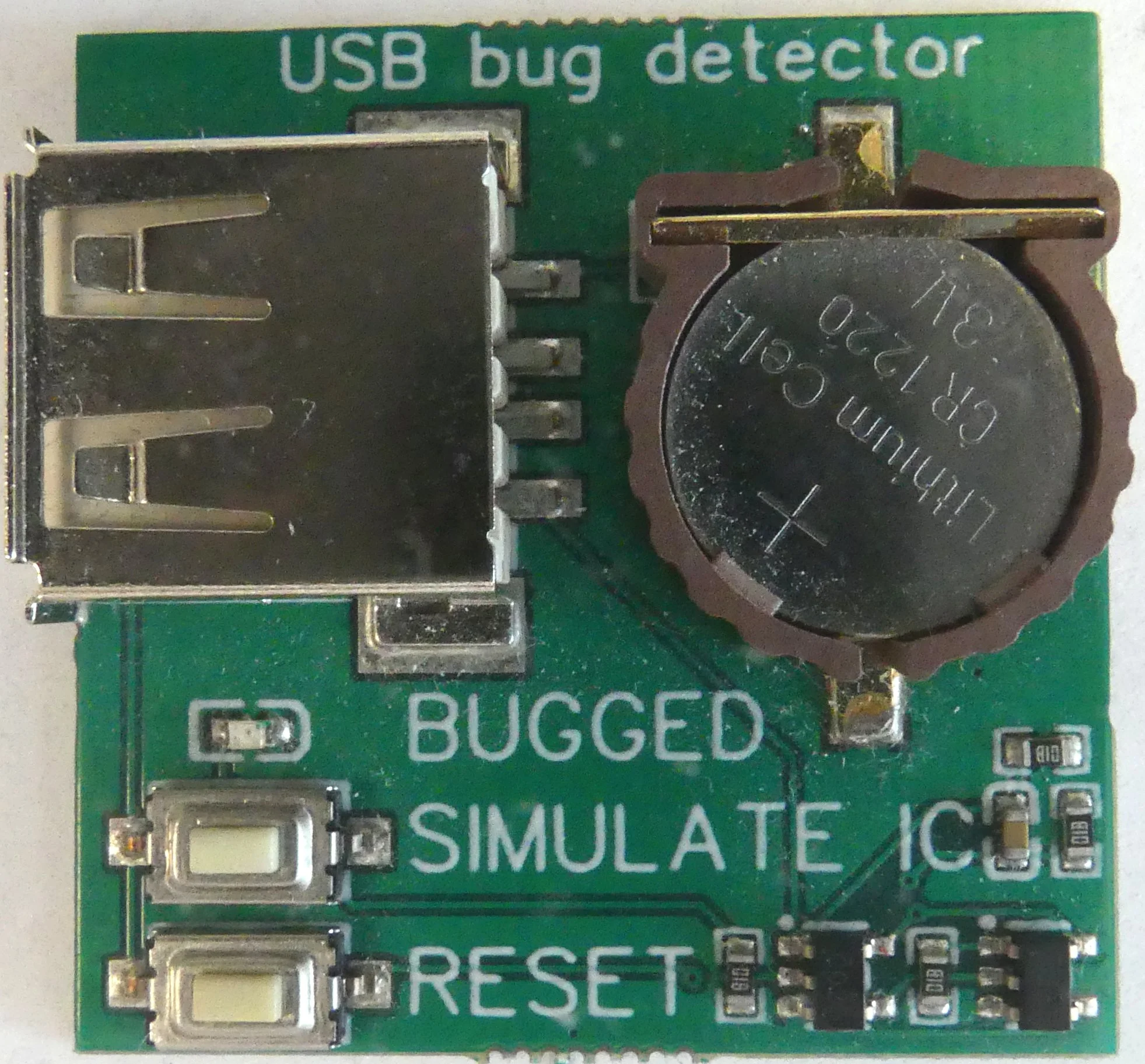
The USB bug detector identifies USB type-A cables (or devices) with integrated circuits.


usage
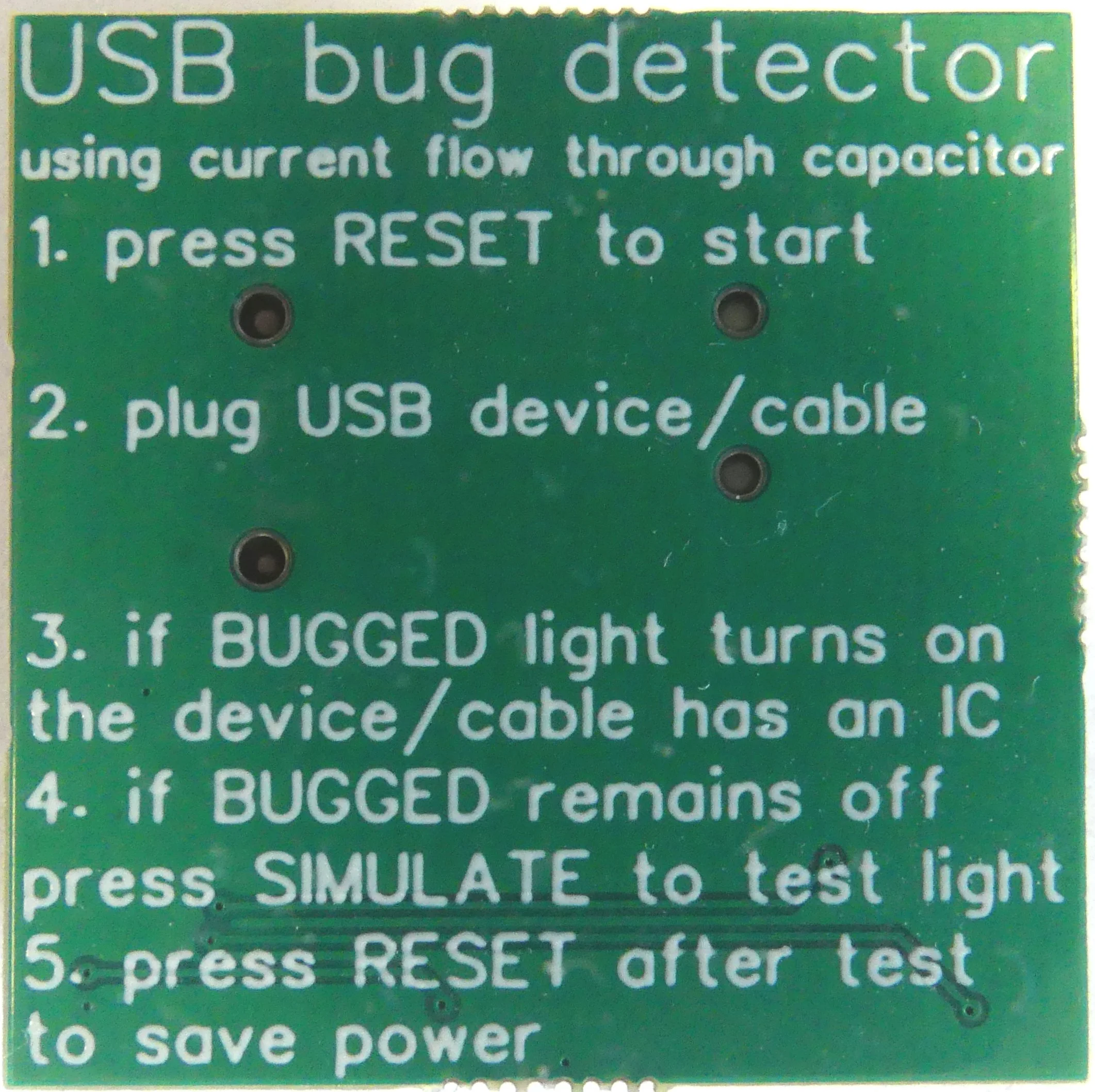
To use the USB bug detector, follow the steps provided on the back of the board:
- insert a CR1220 coin cell battery in the USB bug detector for it to be operational
- press on the RESET button to arm the test
- the BUGGED LED should be off
- plug the USB cable in the USB receptacle
- if the BUGGED LED switches on, the USB cable embeds an integrated circuit (e.g. a bug)
- if the BUGGED LED remains off, the cable is same to use
After the test, to save power, press again on the RESET button.
To ensure that the USB bug detector works, after pressing on the RESET button, press on the SIMULATE button. This will simulate a USB plug with integrated circuit. The BUGGED LED should switch on. This also ensures the battery is not empty.
When the LED is on, the USB bug detector draws 3 mA. When the LED is off, the USB bug detector draws 64 nA. This results in a idle battery life of 62 years (for a typical 35 mAh CR1220 battery). This is on par with the self life of the battery (~ 1%/year).
mode of operation
An NOR-gate-based SR-latch is used. The RESET button triggers the R signal to reset the latch. When a USB cable is plugged, power is provided by the battery to the cable. If an integrated circuits is present, current will flow through. A 1 kOhm resistor on the low side (e.g. ground) will create a voltage. If the plug draws more than 1.6 mA, the resulting 1.6 V will trigger the S signal to set the latch. The BUG LED will indicate when the SR-latch is set. The latch remains set until the RESET button is present. Thus, even if the plug stops drawing power, the LED remains on.
This minimum 1.6 mA current draw is often caused by the decoupling/bypass capacitor required by integrated circuit, or accompanying voltage regulator. When charging, the capacitor acts as a short for a small time, allowing current to flow. On USB plugs with just resistors, or LEDs, the resulting current flow is not large enough.
The SIMULATE circuit simulates an integrated circuit by putting a 100 nF capacitor across the USB receptacle.
Because of the 1 kOhm inline resistor, and limited 3.3 V provided by the battery, a maximum of 3.3 mA can be drawn by the USB plug. This is often not enough to power up integrated circuit properly, particularly if they use a radio interface. Thus it is safe to use the USB bug detector on bugs, without activating it.